Saturday, 26 June 2021

Installing The Electrical Systems (Module 5)


Module 5 - Installing the Speedometer.

The speedometer was a very cheap installation, costing about £25. Remarkable that you can get the electronic speedo plus associated GPS unit so cheaply.


First, a hole was cut to allow the speedo to fit into the the control panel. 

The black wire (negative) from the back of the speedo was run to the negative busbar. 


The red positive wire was connected to the back of the second switch down on the left switch panel.


It's worth taking a few moments to explain how the left switch panel works (see below).


The left switch panel has six fuses on the left, six switches in the middle that illuminate when switched on and six labels, on the right, describing the equipment controlled by the switch.

 As we saw in the first two modules, two cables (one black and one red) arrive at the rear control panel from the battery.
 1. The black is connected to the negative busbar and the red to the positive busbar.
 2. A positive wire was then run from the positive busbar to the left switch panel.
3. A negative wire was run from the left switch panel to the negative busbar.

Effectively, this meant power was now available at all six switches.

We now connect the second switch down, on the left switch panel, to the positive cable (red) on the speedo.
Next, connect the negative (black) cable on the speedo to the negative busbar.

When we move the second switch down, on the left switch panel, to the 'on' position, electricity flows through the 5 amp fuse and then into the speedo, it flows out of the speedo back to the negative busbar, this completes the circuit and the speedo is 'live'. NB the speedo called for a 5 amp fuse and so I replaced the factory installed 15 amp fuse that came with the left switch panel.

Having got electricity to the speedo it only remained to plug the data cable supplied, into the back of the speedo. At the other end of the data cable is a GPS unit that keeps the speedo informed of the distance moved by the boat in a specific time (distance/time = velocity) which translates to the speed shown on the speedo.

I had previously mounted the GPS unit on the top centre of the wheelhouse and fed the data cable to the control panel using the same route as the navigation lights wires

GPS Unit for Speedometer


The final check came by connecting the 
battery and selecting the second switch down, on the left switch panel, to the 'on' position.

1. The second switch glowed red.
2. The face of the speedo illuminated
3  The odometer on the speedo appeared.
4. The numbers on the odometer spun, making a whirling sound
5. The odometer stopped and displayed a number. This means the GPS is in range and working. Otherwise it would have  displayed an error message.


The check went well and the installation of the speedometer was complete apart from the scratches to the woodwork around the speedo which will need filling and painting.

Friday, 11 June 2021

Installing The Electrical Systems (Module 4)

 Module 4 - Install Bilge Pump.

   The bilge pump should have been a much easier job than it turned out to be, thanks to a misprint in the instructions.

I located the pump as far aft as I could and close to the centreline, this being the lowest point in the boat and potentially the deepest point for water coming into the bilges. I glued a piece of plywood to the planks then screwed the base of the pump into the plywood.

Orange topped Bilge Pump

I had wanted the pump to be automatic, to allow increase in water levels to set it off. That way it would empty the bilges even if the boat was unmanned, however, it also had the facility to give a manual switch on/off. As I had an appropriate switch I connected the pump to it.


Auto/Manual/off switch for bilge pump, centre


It was a heck of a job running the cables the length of the boat to the bilge pump control switch on the control panel. Having made the connections, I switched on the power  ... it didn't work! For hours I searched for bad connections but finally gave up.
   Perhaps the pump was broken? But no, it seemed the switch I had was part to blame as it didn't work in manual mode.
   Let me explain how I found the real culprit:
1. The pump had 3 wires, a black (negative), a brown and a brown with white stripe.
2. The instructions tell you to connect the brown white and black to give the automatic operation...this is a misprint, it should say manual operation.
3. Seven lines below it says the black and brown to give automatic. This is why the original set up didn't work.


  I decided to simplify everything. I stripped out the cables and ran shorter lengths of cable direct to the battery. I took the wires through a black conduit to protect them and ran them from the pump up into the battery locker


Whilst the black cable remained black, I extended the brown with red to show 'live'. (all cables on Seagull are Black(-) and Red (+) )

I put in an a 5 amp inline fuse, to protect the pump, then connected the two wires (the thinner ones) to the battery terminals.


I pressed the test switch on the pump and it worked fine! Job Done!

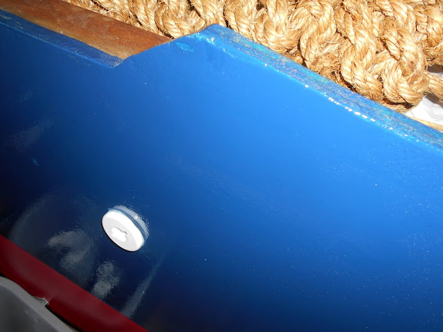
Finally, I drilled a hole in the transom and inserted a gland that had come with the bilge pump. The gland operated like a nut and bolt, with the bolt head being on the outside and the nut inside. I tightened the nut after making sure I had adequate sealant on the faying surfaces.


Inside, I connected the pump drain outlet to the gland in the transom and secured it with stainless steel jubilee clips


Thursday, 25 March 2021

Installing The Electrical Systems (Module 3)

Module Three - Install Port & Starboard Navigation Lights 

The switch unit comes ready wired to the three switches on the switch unit (top left) and three fuses (top middle) (fig 1). All I needed to 

(fig 1)

All I had to do is take a negative wire (black) and attach it to the negative busbar and a positive wire (red) and connect it to the positive busbar (fig 2): the top wires in fig 2.


(fig 2)

Next I took the one available wire from the top switch and extended it by connecting it to a long length of wire wire. The long length was routed up the side of the wheel house and across the top of the forward window. I had left spaces in the wheel house to accommodate the wires (fig 3). I also secured a negative wire to the negative bus and ran it with the read to the nav lights.

(fig 3)

The wires passed though holes behind the Nav lights locations and were secured to the negative and positive points on both lights (fig 4).

(fig 4)

both light were screwed to the outside of the wheelhouse, the battery connected and the top swith turned to on ... the light illuminated. (fig 5 and 6).

(fig 5)


(fig 6)


Wednesday, 24 March 2021

Installing The Electrical Systems (Module 2)

Module Two - Deliver power to controls

In the previous module we delivered 'domestic' power from the battery, in the aft starboard locker, to the electrics panel inside the console in the wheelhouse.

In this module we will take the power from the two terminals we fitted on the electrics panel (fig 1) to the switch units located in the front of the Console .

(fig 1)


(fig 2)


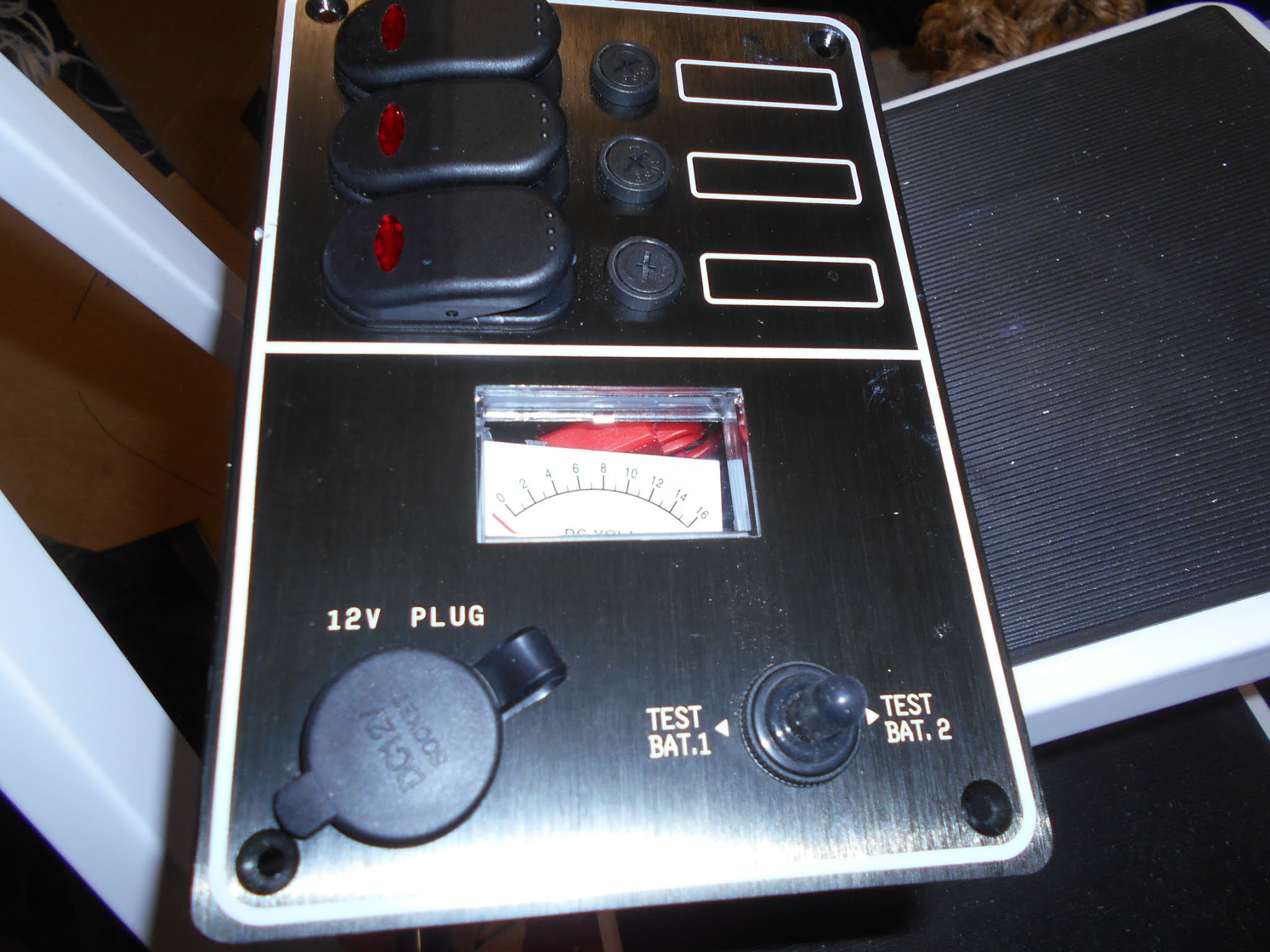
The switch panel comprises three switches, top left, and three circular fuses, centre top. Bottom right is a switch that allows the voltage in Battery 1 to be read in the square window display above it- when moved right - or the voltage to Battery 2 when moved to the left. Finally, at the bottom left  there is a circular 12V plug outlet.
 
The back of the panel (fig 3)shows a series of wires that need attaching to the two terminals (fig 1) we fitted 

(fig 3)

Obviously there are too many wires for only two terminals and so we need to extend range of the terminals by adding two busbars (fig 4): positive bar on right and negative on the left. The negative terminal being connected to the left bus, and positive terminal to the right bus

(fig 4)

Now wires from the switch panel can be attached to bus bars. Electricity will flow from the battery, along the cables to the two terminals, then into the bus bars and through the red wires to the switch panel (fig 5) and back to the battery along the black wires.


(fig 5)


Thursday, 4 March 2021

Installing The Electrical Systems (Module 1)

Module One - Deliver power from battery to system controls).


There are two sources of power on the boat, both sources are batteries. One battery is for engine starting and the other supplies the 'domestic' systems. It is the latter we shall be dealing with in this section.

We have positioned the domestic battery in the aft starboard locker: left as you look at the picture (fig 1 and 2)

(Fig 1)

(Fig 2)

However, the battery power is needed in the console to supply power to  the controls of the systems (lights, navigation etc). For this to happen two cables are run from the battery terminal posts along under the starboard gunwale to inside the terminal.

Previously we had cut a door into the back of the console to give access to a plywood panel that would become the electrics board. (fig 3)

(Fig 3)

Onto the electrics board I screwed a two pole terminal block (fig 4 & 5). These were to become a duplication of the batteries terminal.


(Fig 4)
(Fig 5)


First I took the black (negative) cable and cut off a short length of insulation (Fig 6).

(Fig 6)

 The exposed end was inserted into a copper tube terminal lug (Fig 7) , crimped with a hammer and punch and sealed using heat shrink tube.


(Fig 7)
Heat shrink tube is a thin rubbery sleeve (Fig 8) that is placed loosely over the joint (Fig 9) and shrunk by blowing it with a heat gun to form a tight waterproof joint (Fig 10)


Fig (8)


(Fig 9)


This process was repeated on the red (positive) cable and the cables fed onto the electrical panel  and connected to the two pole terminal (Fig 10)

(Fig 10)


Sunday, 22 March 2020

Steering Gear - Cable Installation Part 2

I didn't take enough photographs of today's final episode of the steering gear installation. Trouble is when you're totally involved in solving the many problems, cameras are the last thing you think of.

Having reached the console with the cable I had the problem of feeding it through the bulkhead and then through 90 degrees to route it behind the control panel to were I was to fit the helm mechanism. The restriction on bends in the cable is they must not be tighter than an 8 inch radius. 
    This part of the operation worked out much easier than I had anticipated. With the minimum of fuss,  through it came. At this point the rubber tube protecting the actual cable was pulled off and discarded and the cable fed into the bottom of mechanism until it could move no further. 


The helm (steering wheel) was now turned and engaged the cable; turning continued and drew the cable right through the mechanism until it appeared through the top aperture of the mechanism. The 12" tube, supplied as a guard, was placed over the cable and the wheel turned until the cable was fully through and engaged with a 'click!'


All that was left to do was insert the two security clips (and instruction label).


Trying to insert these two pins was turning into a nightmare: I was trying to fit them with my fingertips in a small area. I had to rely on feel as I couldn't see past my hands. I had a lunch break and remembered my wife had some tiny long nosed pliers in an earring-fixing kit. They did the trick in a couple of seconds.


It now only remained to re-attach the door.


I just hope the cable is long enough, but I don't think it will be. 


When the engine arrives we will be able to determine if I need a longer cable.

Saturday, 21 March 2020

Steering Gear - Cable Installation Part 1

I have watched a number of cable installation videos and they all seemed straight forward. That was never going to be the case with me! In theory, the cable goes from the helm to the rudder, or outboard motor in my case. If you have bulkheads in the way, you simply drill a hole in them and feed the cable through the hole.

'Seagull' presents a few helpful features, for example: the brackets that connect the hull and gunwales can be drilled allowing the cable to pass through them. This keeps them securely held out of harm and view. 


I decided to feed the cable from the stern despite many advocating that it's best to it from the console back to the stern. My reason is that there is a big coupling at the rudder end that would present a problem when I tried to move it along the routing.


I spent hours drilling and chopping out an aft access-hole, this had to be done by burying myself in the aft locker to work on the spot in question - very cramped and difficult.


After a few tries of the cable, and cutting out more and more, the cable finally began its journey.


Routing the cable through the brackets wasn't a problem.


Tomorrow I will cut cable access holes in the console to join the cable to the steering gear.