Thursday 25 March 2021

Installing The Electrical Systems (Module 3)

Module Three - Install Port & Starboard Navigation Lights 

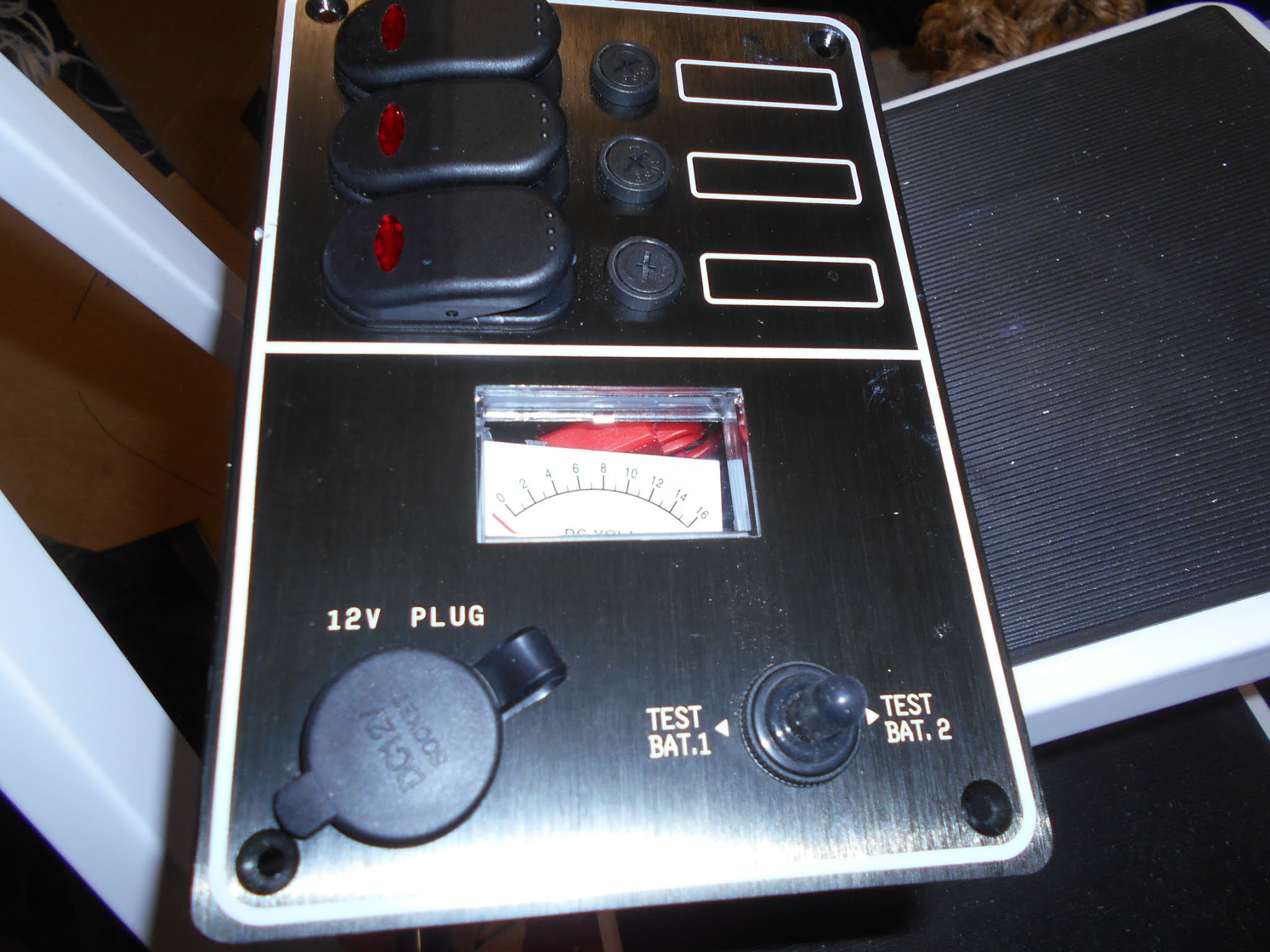
The switch unit comes ready wired to the three switches on the switch unit (top left) and three fuses (top middle) (fig 1). All I needed to 

(fig 1)

All I had to do is take a negative wire (black) and attach it to the negative busbar and a positive wire (red) and connect it to the positive busbar (fig 2): the top wires in fig 2.


(fig 2)

Next I took the one available wire from the top switch and extended it by connecting it to a long length of wire wire. The long length was routed up the side of the wheel house and across the top of the forward window. I had left spaces in the wheel house to accommodate the wires (fig 3). I also secured a negative wire to the negative bus and ran it with the read to the nav lights.

(fig 3)

The wires passed though holes behind the Nav lights locations and were secured to the negative and positive points on both lights (fig 4).

(fig 4)

both light were screwed to the outside of the wheelhouse, the battery connected and the top swith turned to on ... the light illuminated. (fig 5 and 6).

(fig 5)


(fig 6)


Wednesday 24 March 2021

Installing The Electrical Systems (Module 2)

Module Two - Deliver power to controls

In the previous module we delivered 'domestic' power from the battery, in the aft starboard locker, to the electrics panel inside the console in the wheelhouse.

In this module we will take the power from the two terminals we fitted on the electrics panel (fig 1) to the switch units located in the front of the Console .

(fig 1)


(fig 2)


The switch panel comprises three switches, top left, and three circular fuses, centre top. Bottom right is a switch that allows the voltage in Battery 1 to be read in the square window display above it- when moved right - or the voltage to Battery 2 when moved to the left. Finally, at the bottom left  there is a circular 12V plug outlet.
 
The back of the panel (fig 3)shows a series of wires that need attaching to the two terminals (fig 1) we fitted 

(fig 3)

Obviously there are too many wires for only two terminals and so we need to extend range of the terminals by adding two busbars (fig 4): positive bar on right and negative on the left. The negative terminal being connected to the left bus, and positive terminal to the right bus

(fig 4)

Now wires from the switch panel can be attached to bus bars. Electricity will flow from the battery, along the cables to the two terminals, then into the bus bars and through the red wires to the switch panel (fig 5) and back to the battery along the black wires.


(fig 5)


Thursday 4 March 2021

Installing The Electrical Systems (Module 1)

Module One - Deliver power from battery to system controls).


There are two sources of power on the boat, both sources are batteries. One battery is for engine starting and the other supplies the 'domestic' systems. It is the latter we shall be dealing with in this section.

We have positioned the domestic battery in the aft starboard locker: left as you look at the picture (fig 1 and 2)

(Fig 1)

(Fig 2)

However, the battery power is needed in the console to supply power to  the controls of the systems (lights, navigation etc). For this to happen two cables are run from the battery terminal posts along under the starboard gunwale to inside the terminal.

Previously we had cut a door into the back of the console to give access to a plywood panel that would become the electrics board. (fig 3)

(Fig 3)

Onto the electrics board I screwed a two pole terminal block (fig 4 & 5). These were to become a duplication of the batteries terminal.


(Fig 4)
(Fig 5)


First I took the black (negative) cable and cut off a short length of insulation (Fig 6).

(Fig 6)

 The exposed end was inserted into a copper tube terminal lug (Fig 7) , crimped with a hammer and punch and sealed using heat shrink tube.


(Fig 7)
Heat shrink tube is a thin rubbery sleeve (Fig 8) that is placed loosely over the joint (Fig 9) and shrunk by blowing it with a heat gun to form a tight waterproof joint (Fig 10)


Fig (8)


(Fig 9)


This process was repeated on the red (positive) cable and the cables fed onto the electrical panel  and connected to the two pole terminal (Fig 10)

(Fig 10)